Phywe demonstration radio from 1925
. Last update April 4, 2022, Fred Hartjes

|
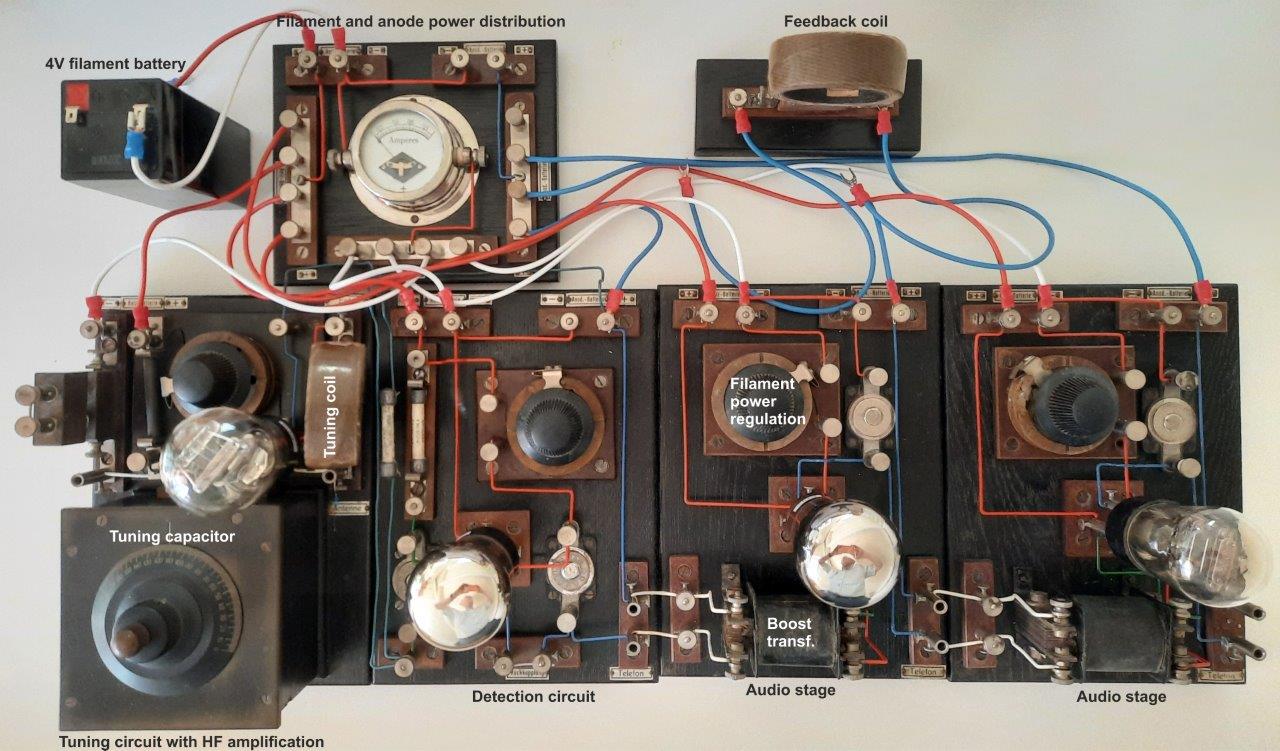
Around 1962, a year after I left my secondary school "Het Willem de Zwijger Lyceum" in Bussum (NL), my highly estimated physics teacher Dr P. Gathier asked me if I could do something with the old demonstation radio the school still had. It appeared to be a black wooden box, fabricated by Phywe, and containing a number of black wooden boards populated with chromed wire clamps, tubes, transformers and other electronic components from about 1925, the very early stage of radio technology. The connections were made by solid copper wires painted in four different colours. I don't remember if I succeded at that moment to get some life out of it, but seven years later I still got it into operation. Now some five decades afterwards, being retired from Nikhef, I found time to look more into detail of this fascinating assembly. After a restauration like thorough cleaning and repairing the potentiometers with the original Ni/Cr tape, I looked with modern electronic tools at the functioning of the set-up. The assembly consists of 6 wooden boards with the following functions.
There was no manual but the assembly was well described in an article by Dr. Gotthelf Leimbach in the magazine "Praktische Schulphysik" 5/1 (1925) p1-10 that was enclosed. The amplification of the signal is done using triode radio tubes, in 1925 the first available electron tubes with amplification by using a grid. Detailed information about the functionning of electron tubes and all kind of other information about the radio technology at that time is found in the extensive book of Dr Eugen Nesper: Der Radio-Amateur. |
 |
|
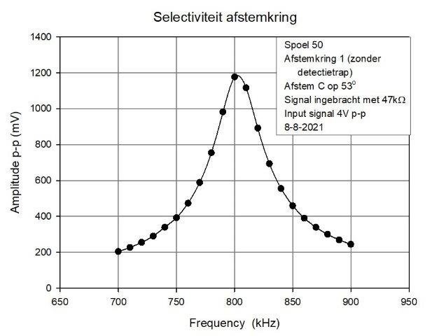
Selection of the desired broadcast frequency is done by an LC circuit of an adjustable capacitor and an inducter coil. Of course the selectivity of such a circuit is limited. The plot on the right hand shows as an example that the FWHM of the peak adjusted at 800 kHz is about 65 kHz, so the radio is not well capable to distinguish a rather weak radio station from a strong nearby one. The demonstration radio set contains 8 different coils of 35, 50, 75, 100, 150, 200, 250 and 300 windings. In combination with the adjustable capacitor one gets a tuning range from 100 - 1400 kHz or 3000 - 215 m. 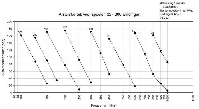
|
|
|
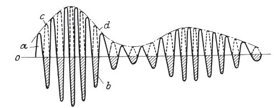
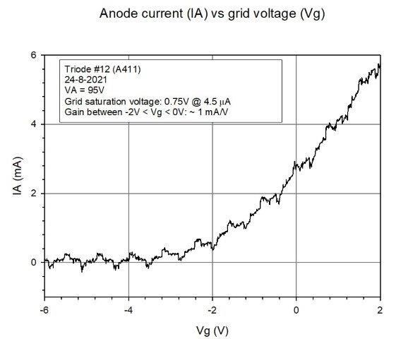
Detection of the Amplitude Modulated (AM) radio signal, i.e. extraction of the audio signal from the carrier wave, occurs by using the bend in the anode current curve as a function of the grid voltage. The principle is shown on the picture above where the negative part of the radio signal is removed by using the absence of amplification for negative potentials. If subsequently the high frequencies are blocked by filtering, only the audio frequencies remain. The right hand picture shows a typical measurement of the IA curve of one of the available triodes. The curve shows that for grid potentials under -2 V the amplification is almost absence, so the AM audio signal of radio signals inserted at an average grid voltage of -2V are well separated. However, since the bend of the IA vs Vg curve is quite soft, this only operates for radio signals larger than several hundred mV. Smaller radio signals can only be detected after a substantial amplification. The demo radio assembly did indeed have a single high frequency stage at the board with the tuning circuit. But the HF amplification of the radio tube did not offer sufficient amplification to make this useful. Therefore, the demo radio can only produce an audible sound when a sufficiently large radio signal is available. Since at present in the Netherlands, only a limited number of remote AM senders are available, broadcasting at a low power, the functioning of the demo radio can no longer be demonstrated with an actual radio signal. |
|